

 Toolpath Selected Shapes
To use this function first select closed shapes on the screen. These must have been previously processed using the cleanup and hierarchy functions for this function to work correctly. By supplying appropriate machining parameters through the Choose Toolpathing Parameters dialog box, a toolpath will be generated. This must be done before the nesting and output to machine stages. The user can also save the toolpathing parameters as a template.
Note: The specific toolpathing options depend on the current machine configuration, but the following are typical examples.
Plasma Toolpathing Settings
1. Cutting Settings
Tool Name
The name of the current tool
Tool Number
Tool changer number
Cut Width
The width of the cut.
Arc Volts
Plasma power setting.
XY Feed Rate
The XY feed rate.
Pierce Delay
The time taken before the tool moves, after piercing the material.
Pierce Height
The clearance between the torch and the material during the piercing process.
Over burn / Underburn
This setting can be used to configure how cutting is finished for individual shapes. Define over burn by entering a positive value in and underburn by entering a negative value. The unit is mm.
Default value is zero.
Has Sharp Corners?
Specify whether sharp corners are used in toolpathing. Default setting is Yes.
2. Open Path Toolpathing
Apply toolpath to open contours?
Select Yes or No.
Offset Direction
Centre: The toolpath will follow the path of the open-contour.
Left: The toolpath will provide the cutting path to the left of the open-contour.
Right: The toolpath will provide the cutting path to the right of the open-contour.
3. Lead-In / Lead-Out
Lead-in Type
Select Straight, Arc or None.
Lead-in Length
The length of the lead-in.
Lead-in Angle
The angle of the lead-in.
Lead-out Type
Default value is None.
4. Pre-Piercing
Perform Pre-Piercing?
Specify whether pre-piercing is performed.
Tool Name
The pre-piercing tool name.
Tool Number
The pre-piercing tool number.
Arc Volts
Plasma power setting for pre-piercing.
Pre-piercing Offset
Pre-piercing offset in mm.
Pierce Delay
The time taken before the tool moves, after piercing the material.
Pierce Height
The clearance between the torch and the material during the piercing process.
Note: Travelling Speed and Travelling Height global settings can be configured through Options \ Preferences menu selection.
Figure 30: Example of toolpathing parameters for thick material cutting. Plasma cutter is used for pre-piercing and then Flame cutter for the actual cutting.
Router Toolpathing Settings
1. Cutting Settings
Tool Name
The name of the current tool
Tool Number
Tool changer number
Cut Width
The width of the cut.
Depth
The depth of the cut.
XY Feed Rate
The XY feed rate.
Z Feed Rate
The Z feed rate.
Dwell
The time taken before the tool moves, after piercing the material.
Spindle Speed
The speed of the spindle.
Ramp Leadin?
Select Yes or No. This setting is for tools that cannot plunge vertically.
Conventional / Climb
Climb milling and conventional milling are terms used to describe the direction in which the shape is cut. If the external edge of the shape is being cut out in an anticlockwise direction, this is called conventional milling. If the external edge of the shape is being cut out in a clockwise direction, this is called climb milling.
Overcut / Undercut
This setting can be used to configure how cutting is finished for individual shapes. Define overcut by entering a positive value in and undercut by entering a negative value. The unit is mm.
Default value is zero.
Has Sharp Corners?
Specify whether sharp corners are used in toolpathing. Default setting is Yes.
2. Open Path Toolpathing
Apply toolpath to open contours?
Select Yes or No.
Offset Direction
Centre: The toolpath will follow the path of the open-contour.
Left: The toolpath will provide the cutting path to the left of the open-contour.
Right: The toolpath will provide the cutting path to the right of the open-contour.
3. Lead-In
Lead-in Type
Select Straight, Arc or None.
Lead-in Length
The length of the lead-in.
Lead-in Angle
The angle of the lead-in.
Lead-out Type
Default value is None.
4. Pre-Piercing
Perform Pre-Piercing?
Specify whether pre-piercing is performed.
5. Multiple-Pass Settings
Number of Passes.
Define the number of passes to reach the final depth.
Continuous Spiral?
Select Yes or No. This will cause the cutter to spiral down to the final depth.
Use a Cleanup Pass?
Select Yes or No.
Cleanup Offset
Primary cut is offset this amount from the shape. The Cleanup pass removes this material and polishes the edge of the part.
Cleanup Pass Thickness
Primary cut path leaves this amount of material at the bottom of the cut. Cleanup pass removes this material.
7. Inlay
Toolpath for Inlay?
Select Yes or No. This option modifies the corners of the part so that inlay pieces will fit into cut out. This option should be used for male and female parts.
Inlay Radius
This specifies the amount of rounding for inlay corners. This should be equal or larger than the cutter radius. The same setting must be used for male and female parts.
Overlap thickness
Overlap between inner and outer toolpaths.
Note: Travelling Speed and Travelling Height global settings can be configured through Options \ Preferences menu selection.
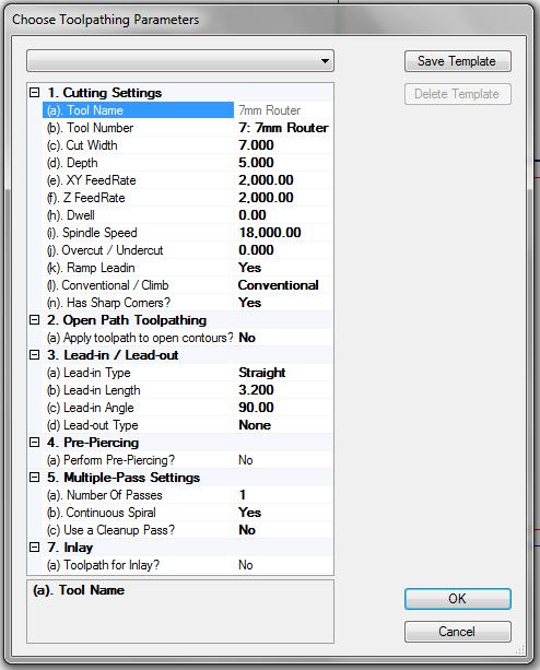
Figure 31: Example of toolpathing parameters for a router tool.
Figure 32: Section of a toolpathed shape with 10mm straight lead-in in one of its holes.
Note: You can add additional toolpaths to the selected objects by repeating the “Toolpath Selected Shapes” function. The program asks first users acceptance. You will see this same message also if your current selection already contains some shapes with a toolpath and you are adding a new toolpath.
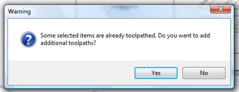
Figure 33: By repeating the “Toolpath Selected Shapes” function you can add additional toolpaths.
 Toolpath for Drills / Piercing
This function opens the “Choose Drill Toolpathing Settings” dialog box which allows user to activate the drill point placement mode or to toolpath selected closed shapes for drill or piercing. If you are toolpathing selected shapes for drill they must have been previously processed using the cleanup and hierarchy functions for this function to work correctly.
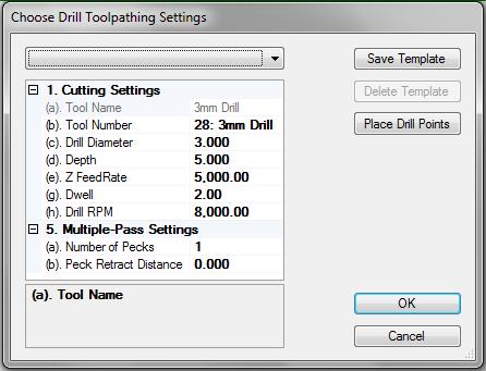
Figure 34: Toolpathing Parameters dialog for drill toolpath.
Choose the drill settings you wish to use to toolpath selected shapes or to use in the drill point placement mode.
Note: If you are using a tapping tool together with a drill, please select tapping tool as the main tool and the drill as the pre-piercing tool.
Drill Toolpathing Settings
1. Cutting Settings
Tool Name
The name of the current tool
Tool Number
Tool changer number
Drill Diameter
The diameter of drill.
Depth
The distance to drill.
Z Feed Rate
Plunge speed.
Dwell
The time taken before the tool moves, after piercing the material.
Drill RPM
Drill revolutions per minute.
2. Open Path Toolpathing
Apply toolpath to open contours?
Select Yes or No.
4. Pre-Piercing
Perform Pre-Piercing?
Specify whether pre-piercing is performed.
5. Multiple-Pass Settings
Number of Pecks
Specify the number of drill pecks.
Peck Retract Distance
Distance the drill retracts after each peck.
Note: Travelling Speed and Travelling Height global settings can be configured through Options \ Preferences menu selection.
Drill Point Placement Mode
After you have selected the appropriate drill settings click on the “Place Drill Points” button on the “Choose Drill Toolpathing Settings” dialog box to enter drill point placement mode. The mouse cursor changes to cross-hair cursor indicating a valid placement. You can now start placing the drill points by left mouse clicking on the desired locations. If you move the mouse cursor near the edge of an existing drill point then the mouse cursor changes to select cursor which allows you to select the drill point.
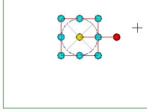
Figure 35: Placing drill points by left mouse clicking.
Change the drill settings while placing drill points via drill point placement popup menu. To access the popup menu right click anywhere on the screen. After modifying the settings you may accept them by clicking “OK” button or you may discard them by clicking “Cancel” button. Clicking either button will return you back to the drill point placement mode.

Figure 36: During the drill point placement you can change the drill settings via a popup menu.
Continue Placing Drill Points
Returns to the Drill Point Placement mode where you can add new drill points.
Cancel
Cancels the Drill Point Placement mode and switches ToolShop back to the main Mouse Selection mode.
Edit Drill Settings
Goes back to the “Edit Drill Settings” dialog where you can change the drill settings.
Note: While you are in the Drill Point Placement mode you can remove any selected drill point by pressing the Del key on the keyboard.
 Centre-line Toolpath Selected Shapes
The settings for centre-line cutting are same as for offset cutting. However with centre-line cutting the tool follows the centre of the toolpath. This is same as defining tool offset as zero.
 Fills
Fills
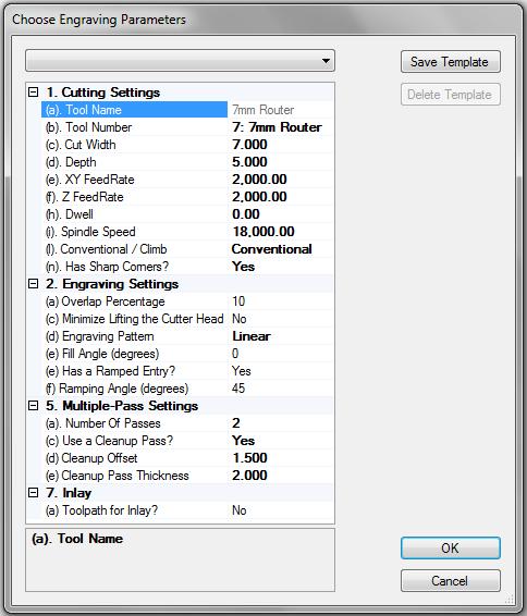
Figure 37: Typical settings for hatch filling.
Fills Settings
1. Cutting Settings
Tool Name
The name of the current tool
Tool Number
Tool changer number
Cut Width
The width of the cut
Depth
The depth of the cut
XY Feed Rate
Feed rate at which the machine will travel while it is cutting through the material. This does not affect the rapid feed rate of the tool when it travels above the surface of the material.
Z Feed Rate
Feed rate at which the machine will plunge into the material in a vertical direction. This does not affect the XY feed rate or the rapid feed rate of
the tool when it travels above the surface of the material.
Dwell
The dwell value denotes how long the machine will pause at the end of the first plunge of each shape. Its unit of measurement is seconds.
Spindle Speed
Spindle RPM
Conventional / Climb
Conventional and climb milling are terms used to describe the direction in which the shape is cut. If the external edge of the shape is being cut out in an anticlockwise direction, this is called conventional milling. If the external edge of the shape is being cut out in a clockwise direction, this is called climb milling.
Has Sharp Corners?
Specify whether sharp corners are used in toolpathing. Default setting is Yes.
2. Engraving Settings
Overlap Percentage
Default value is 10.
Minimize Lifting the Cutter Head
Self-explanatory
Engraving Pattern
Linear (Hatch fill) or Island fill.
Fill angle (degrees)
This is the angle for linear fill pattern. Default value is 0.
Has a ramped entry?
Select Yes or No. This setting is for tools that cannot plunge vertically.
Ramping angle (degrees)
5. Multiple-Pass Settings
Number of Passes
Default value is 1.
Use a Cleanup Pass?
Select Yes or No.
Cleanup Offset
Primary cut is offset this amount from the shape. The Cleanup pass removes this material and polishes the edge of the part.
Cleanup Pass Thickness
Primary cut path leaves this amount of material at the bottom of the cut. Cleanup pass removes this material.
7. Inlay
Toolpath for Inlay?
Select Yes or No. This option modifies the corners of the part so that inlay pieces will fit into cut out. This option should be used for male and female parts.
Inlay Radius
This specifies the amount of rounding for inlay corners. This should be equal or larger than the cutter radius. The same setting must be used for male and female parts.
Overlap thickness
Overlap between inner and outer toolpaths
Note: Travelling Speed and Travelling Height global settings can be configured through Options \ Preferences menu selection.
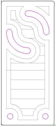
Figure 38: A picture of a shape that was linear filled by using 12mm wide routing tool
and 180 degree fill angle
Note: If user has selected Inlay toolpathing and if the “Inlay Chamfer Radius” is smaller than the radius of the cutter then ToolShop shows a warning. See Figure 39.
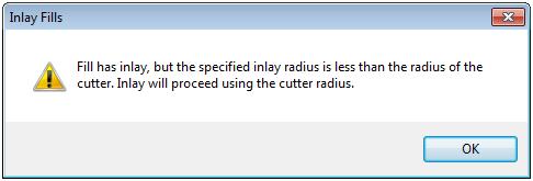
Figure 39: If user is toolpathing for inlay and the “Inlay Chamfer Radius” is smaller than the radius of the cutter then the radius of the cutter is used instead.
 Toolpath Text for Print Head
This function specifically supports D.O.D. style inkjet text printers with or without a rotating axis. Most ART Routing and Plasma cutting machines may be fitted with this device for marking part numbers and fold lines etc. Other brands of machines may be supported if this type of accessory is available for that model.
To use this function first select text objects on the screen. Click the Toolpath Text for Print Head toolpath button to display the toolpath dialog.
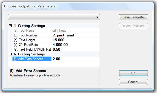
Figure 40: Typical settings for print head toolpathing.
Note : As most text printers have limited font sizes, these text objects should already be drawn in the CAD program at the correct height to match the printer capabilities. This is important so that ToolShop can display an accurate layout on the screen i.e. if the printer prints 14mm high letters, then the drawing should have 14mm high text.
Print Head Toolpathing Settings
1. Cutting Settings
Tool Name
The name of the current tool
Tool Number
Tool changer number
Text Height
Text height should be same as the printer font.
XY Feed Rate
XY feed rate should match the maximum printing speed. (Usually around 4000)
Text Height/Width Ratio
The ratio should be the printer character width / character height .
(Usually around 0.50)
Add Extra Spaces
This is a small buffer to ensure the baseline is longer than the printed text. (Usually 2 extra spaces)
Note: These values normally do not change from job to job. The defaults should be setup correctly in the Options / Tool Settings dialog.
 Edit Toolpath
This function shows a dialog similar to “Toolpath Selected Shapes” dialog and allows you to edit toolpathing parameters for selected shapes. After accepting the changes the objects are re-toolpathed.
 Delete Toolpaths
This function is provided to delete previously generated toolpaths from selected objects. Use this option to alter the toolpath settings on an object or exclude a particular object from the CNC file output to the machine.
 Move Start Points and Lead-ins
Enabling this function will display a marker at the start position for each toolpath. Move each marker with the mouse by dragging it along the toolpath to a new location. Ensure that the position of the start point is not on top of another object.
It is good practice to position the start points on a corner. Correct positioning of start points is critical for good machining. It is also useful to ensure that other shapes are not cut when piercing through the material. Perform this function after nesting.
Figure 41: Start point markers indicating the lead-ins. Move each marker with the mouse.
 Link Cutting
Enabling this function allows the user to ‘link’ several shapes together to reduce the number of start points on plasma tools. This can dramatically increase the life of the consumables. While this is very desirable, it must be used carefully. Usually, several parts will be positioned around in a circle, or alternatively in a couple of rows. You must use the Lead-In and Lead-Out options with this function. Usually a lead-in of 45 degrees and a lead-out of 45 degrees would be desirable. The Lead-Ins need to be positioned in the space between the parts to be linked together. After selecting the Link Cutting function you can click and hold the mouse on any lead-in. The program will automatically display any other start points that are compatible to be linked to the first shape. By dragging the mouse to the next desired start point and releasing the mouse button, ToolShop will display a link between the two shapes. This may be repeated as many times as desired.
After two or more shapes are linked, they are locked together and may only be moved as a group. You may still edit the lead-in positions however.
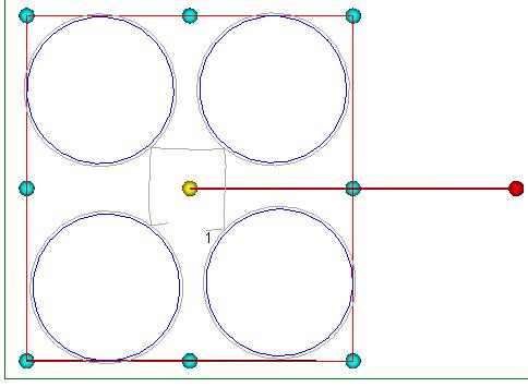
Figure 42: Using link cutting to cut 4 shapes. Both Lead-in and Lead-out are 45 degrees. Notice that the Lead-ins are positioned in the space between the parts to be linked together. By enabling the “View / Cut Order” from the menu you can also check the start point of the linked cutting.
Right mouse click on top of a link line. This will show you a popup menu that enables you to remove links between shapes.
Continue Linking Toolpaths
Goes back to the Link Cutting mode where you can add new links or remove existing links.
Cancel
Cancels the Link Cutting mode and switches ToolShop back to the main Mouse Selection mode.
Remove Link
Removes the link.
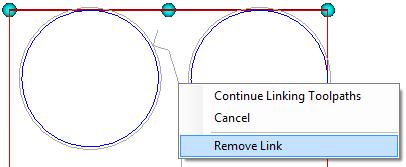
Figure 43: Removing a link.
Note: Delete Toolpath function will remove the links.